Saturday, October 16, 2021

PLC and SCADA Systems

 PLC and SCADA Systems 

As time is passing we are becoming more dependent on software. Software is playing a vital role in the growing development of the world. Friends, today we will talk about those systems which are most needed in industries to run smooth, easily control of any production line or machines and home appliances based on program feeding. Please understand, if we could control the home appliances like AC, Fan, lights etc. through computer, then it would be best. 
So, let's know about PLC and SCADA Systems. 
SCADA System

PLC : 

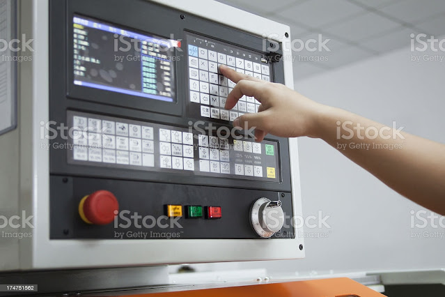
It means Programmable Logic Controller. The widespread application of microcomputers and programmable logic controllers (PLCs) has replaced the factory floor. It is a digital controller that enables to control the machine by input and output devices. When we want to control or operate a machine in a desired manner, then we will need a PLC (Programmable Logic Controller). Multiple input and output devices can be combined with a PLC. After installing PLC in machine, we can operate in better way, also take desired outcomes from machine. In that reason, it is very beneficial. 
PLC (Programmable logic Controller)

PLC helps to convert operation process happening in real time. In this we do not have to change any hardware. That is, it increases adaptability and changeability as compared with hardware. If the machine is in running condition in this production line it collects and gives the data to us. 

HOW DOES PLC (PROGRAMMABLE LOGIC CONTROLLER) WORKS? 

There are 4 basic operational steps for every PLC :- 

1. INPUT SCAN : 

It scans all the inputs connected to the PLC and takes data from them and gives it for output. 

2. PROGRAM SCAN : 

Its work is to implement the program that is input inside the PLC. That is, taking the input under it and converting it to the output. That's the Program scan. 

3. OUTPUT SCAN : 

It gives instructions to the output devices as to which device to run based on the given data. That's the output scan, either energy and de-energizes all connected devices.

4. HOUSEKEEPING : 

This unit is committed to communicate with its internal elements. Only then processing is possible. 

What is input and output devices? 

INPUT DEVICE: 

An input device is a piece of equipment in a computer hardware system that is used to provide data and control signals to an information processing system. 

Types of input devices : 

There are 2 types of input device are as follows: 
  1. Switches 
  2. Sensors 

1. Switches : 

Here some example of input devices like switches such as: 
  • Switches and push buttons 
  • Limit switches 
  • Vacuum switches 
  • Temperature switches 
  • Level switches 
  • Pressure switches etc. 

2. Sensors: 

Here some example of input devices like sensors such as: 
  • Sensors and transistors 
  • Proximity sensor 
  • Photo electric sensor 
  • Condition sensor etc. 

OUTPUT DEVICE : 

An output device is a piece of hardware system used by an IPS to communicate the results of data processing and to translate the information into an understandable form. 
Some examples of output devices are like: 
  • Valves 
  • Motor starter 
  • Horns and Alarm 
  • Control relays 
  • Stack lights 
  • Pumps 
  • Printers 
  • Fans etc. 

SCADA : 

The full form of SCADA is Supervisory Control and Data Acquisition. It is a graphic that supervise the overall system and also collect overall data. At assembly production line, with help of all sensors, SCADA system is collect all information that input from sensors and showing images at a screen that missing cases, wrong assembly, BOPs or other child parts assembly not done at correct position. It is a system of software and hardware elements that interfaces with all the PLCs through the network. SCADA system include a human interface, usually in a central location such as a control room, to monitor processes, generate alarms, and allow the operator to intervene or override as needed. 
This situation has given rise to large-scale supervisory control and data acquisition (SCADA) systems. 

Supervisory Control and Data Acquisition image


Fundamental basics of a SCADA System: 

SCADA (Supervisory Control and Data Acquisition) is allowing industrial organisations to: 
  • Control the industrial process locally or by remotely. 
  • Monitor, gather, and process the real time data 
  • Direct interaction with output devices such as pumps, motors, sensors, valves and more through HMI (Human Machine Interface) software 
  • All these events or data store in log file. 

The basic Architecture of SCADA System: 

The basic architecture of SCADA system starts with PLC (Programmable Logic Controller) and RTU (Remote Terminal Unit). PLC and RTU are microcomputers which communicate with the interface of external devices like machinery, sensors, HMI (Human Machine Interface) and then transfer the information from these external devices to SCADA software based computer. The SCADA system collects, processes and distributes all the information, displays data that helps to analyze the data for the operator or other employee so he or she makes the necessary decisions. 

We hope you will understand this topic. 

Thank you. 

Some important question that you should read to improve skill:- 

Thursday, October 7, 2021

Injection moulding defects & their remedies | QSQTECH.COM

INJECTION MOLDING DEFECTS & THEIR REMEDIES:

Hello friends, 
Today, We'll discuss on Injection molding defects & how to fix them. Hopefully, you'll understand this topic.
First of all, thanks for visiting.
Now, below topics that we are covering today. 
  • INTRODUCTION
  • MOST COMING INJECTION MOLDING DEFECTS
  • CAUSES & THEIR REMEDIES

INTRODUCTION: 

Defects is an error which comes in any machine, mold, material, system and also anything else.  In other words, Defects or problem is an opportunity for improvement. 
According to customer point of view, if any product or service are not meet their specifications, then the product called defective or defect. 
OR 
Defect is an error that hit on any system fitment and functional.

MOST COMING INJECTION MOLDING DEFECTS: 

Injection molding defects are as given below:
  1. SHORT MOLDING 
  2. FLASH 
  3. BURN MARK 
  4. FLOW MARK
  5. AIR BUBBLE 

CAUSES & THEIR REMEDIES

1. SHORT MOLDING: 

Short molding occurs when the flow of molten material cannot completely fill the cavities in the mold. Short molding is comes at that place where material flowing into cavity reach at last filling area. 

Short molding

Ⅰ. Cause: 

  1. The flow of molten material into the mold is restricted by narrow or blocked gates.
  2. If the material is too viscous or the mold is too cold, the molten material is not allowed to completely fill the mold.
  3. Sometimes the trapped air pockets into mold may restrictions proper flow.
  4. The injection pressure may be insufficient or low as per specification. 
  5. Auxiliary equipment like MTC or HRTC malfunctioning & no alarm implement for when temperature disturb. 
  6. Process was not running as per standard set parameters or going out of spec. as compared to standard set parameters. 
  7. Molten material was leakage from nozzle tip as nozzle tip was not matching properly with sprue bush and dent mark on tip or wear out of nozzle tip dia. 
  8. Sprue bush rotate from its actual position. 

Ⅱ. Countermeasures

<Molding equipment>
  1. Make sure that the nozzle is not clogged. If the nozzle clogs frequently, increase the mold temperature or shorten the cycle time. 
  2. Increase injection speed
  3. Increase cylinder temperature setting. Also increase the nozzle temperature. 
  4. Increase the feeding amount of material. If material feeding is still insufficient at maximum material feed capacity, change to a larger capacity machine. 
  5. Install a screw with a back-flow check valve.
  6. Raise the cylinder temperature setting. Also raise the nozzle temperature.
  7. Make sure there are no cut lines in the heater. 
  8. To prevent material from cooling too rapidly, increase the mold temperature. 
  9. Make sure that nozzle tip is properly match with sprue bush. If any leakage found then check the allignment of nozzle tip and sprue bush. Check the nozzle tip dia size. 

<Mold> 
  1. Raise the mold temperature. 
  2. Increase the mold gas release. 
  3. Increase gate cross-section area. 
  4. Increase the molded product thickness. 
  5. Add ribs to the molded product design to enhance flow capacity. 
  6. Check the sprue bush and it should not be rotate from its actual position. 


<Material> 
  1. Choose a low-viscosity high flow material type. 
  2. Apply surface lubricant. (Add 0.05-0.1% by weight). 


2. FLASH: 

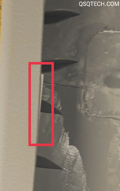
Flash is a defect in an injection molding part, occurring only where two cavities of the mold meet. Flash is found at the location where the mold separates.
It looks like a thin layer on the molded part. 

Flash

Ⅰ. Cause

1. Low clamping force.
2. Insufficient injection pressure. 
3. Mold cavity wear & tear. 
4. Mold life complete as per its capacity. 
5. Improper venting 
6. Gap between core and cavity of the mold.
7. High barrel temperature

Ⅱ. Countermeasures 

<Molding equipment> 
1. Increasing the plate clamping force or moving the mold to a machine with higher clamping force can solve this issue. 
2. Ensure that the mold is properly maintained and cleaned.
3. Ensure that injection pressure is lower than clamping force.

3. BURN MARK : 

Burn mark is an injection molding defect that comes generally in injection molding process. This defect is generally creates due to the burn of the material at a particular place on last filling area in the mold due to some reasons. It may be a small, dark and black spot in appearance. Sometimes, this is happening because when air or gases are not release properly through air vent. 
The air remaining during the pouring of the material into the cavity of the mold is compressed and produces a burn mark on the last filling area. 

Burn mark injection molding defect


Ⅰ. Cause 

  1. Insufficient injection speed
  2. Insufficient injection pressure
  3. High Melt/barrel temperature and mold temperature
  4. Air vent blockage or air not release through venting into mold. 
  5. Foreign material mixing
  6. Presence of Moisture in material 

Ⅱ. Countermeasures 

<Molding equipment> 
  1. Decrease injection speed 
  2. Decrease injection pressure 
  3. Decrease mold/melt temperature 
  4. To improve venting, reduce the clamp force. 
<Material> 
  1. Use the material after pre drying into hopper drier. 
  2. Each material having its own different property, place all material separately. 

4. FLOW MARK : 

Flow mark is an injection molding defect that is
generally, comes when molten material flowing into large variation of cooling speed between sections into mold. It means lack of compensated material during packing stage.
Flow mark is wavy lines or streaks and off tone pattern in appearance. It is also known as Flow line. 

Flow mark


Ⅰ. Cause

  1. Low injection speed 
  2. Low injection pressure 
  3. Low melting temperature 
  4. Low mold temperature 
  5. Small runner stem and gate 

Ⅱ. Countermeasures 

  1. Increase injection pressure 
  2. Increase injection speed 
  3. Increase gate size and runner system for specific mold and material 

5. AIR BUBBLE : 

Air bubble is an injection molding defect that is similar to blister in appearance in that there is air trapped into the molded part. Material over heating into mould is general root cause of air bubble.
There are many reasons to occur this defect. 

Air bubble injection molding defect


Ⅰ. Cause

  1. High mould temperature 
  2. Material over heat 
  3. Air vent blockage 
  4. Cooling trapped into mold 
  5. Material contamination or foreign material mixing 
  6. Cooling line restricted 
  7. High injection speed 
  8. Moisture in material
  9. Small shot size

Ⅱ. Countermeasures 

  1. Decrease injection speed
  2. Decrease injection temperature
  3. Decrease mold temperature
  4. Increase shot size
  5. Pre drying material before molding 
We hope you will understand this topic.

Thank you. 

Some important question that you should read to improve skill:- 
Friday, October 1, 2021

Vernier Height Gauge | How to use Vernier Height Gauge?

VERNIER HEIGHT GAUGE

Hello guys,
Today, We'll discuss on Vernier Height Gauge. 
Lets start discussion on this topic. Hopefully, you'll understand this topic.
First of all, thanks for visiting. 

Below topics that are covering:
  • INTRODUCTION
  • CONSTRUCTION
  • FIND OUT THE LEAST COUNT OF VERNIER HEIGHT GAUGE?
  • HOW TO USE VERNIER HEIGHT GAUGE CORRECTLY?

INTRODUCTION: 

Vernier Height Gauge is a measuring device which is used for measurement of height of any object and marking done by help of scriber. It is based on the principle of "Difference between main scale and vernier scale like "Vernier Caliper". Its least count is 0.02 mm or 0.001".
Vernier Height Gauge is made of stainless steel or mild steel. Its specification is based on beam length. It generally available upto 300 mm of length.

Vernier Height Gauge


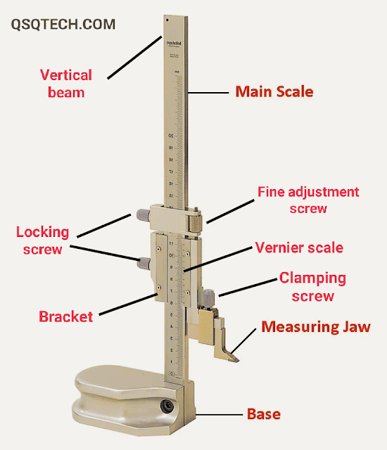
CONSTRUCTION: 

There are many components that are assembled and make this instrument useful in industrial sector.

1. Base 
2. Vertical beam
3. Main scale
4. Sliding bar (Bracket)
5. Vernier scale
6. Fine adjustment screw
7. Locking screw
8. Clamp/Clamping screw
9. Scriber

1. Base:- 

It is a rigid base that is important role play in balancing all the components assembly of instrument. It provides the datum surface which is given reference for marking.

2. Vertical beam:- 

Vertical beam is mounted on rigid base of instrument. Sometimes, it is also known as vertical bar and used to support the main scale.

3. Main scale:- 

Main scale is calibrated in inches on the left side of scale. It is calibrated in cm on the right side of scale. It is Vertically attached with Vertical beam. 

4. Bracket (Sliding bar):- 

It slides on Vertical beam and used to attach the vernier scale and helps to make the vernier scale as a moveable scale. Its one hand is scriber and other hand is fine adjustment screw.

5. Vernier scale:- 

Vernier scale has readings at both side (Right side & Left side). 

6. Fine adjustment screw:- 

This screw is used for adjustment of vernier scale during measurement. It helps to take readings accurately.
 

7. Locking screw:-

We used locking screw to lock the movement between main scale and vernier scale so that we can easily measure the dimensions of any object. It gives accuracy in taking measuring data.

8. Clamp/Clamping screw:- 

Clamp is used to joint the Jaw and sliding bar with help of clamping screw. 

9. Scriber:- 

Scriber is a tool which is used to mark on object at any dimension/measuring point.

Read also:-

FIND OUT THE LEAST COUNT OF VERNIER HEIGHT GAUGE? 

50 vernier scale readings is equal to 49 main scale reading.

Least count = 1 Main scale division - 1 Vernier scale division

1 Main scale division = 1 mm

1 Vernier scale division = 49/50 mm
= 0.98 mm

Least count = 1 mm - 0.98 mm = 0.02 mm


HOW TO USE VERNIER HEIGHT GAUGE CORRECTLY?

1. It should be employed by placing on surface plate. 
2. Surface plate should be properly cleaned. 
3. To avoid mistakes, readings should be write down in same time. 
4. Now, When scribe bottom surface touch surface plate level then zero lines of vernier scale should be coinside with zero line of main scale, both scale (Vernier scale and main scale) having zero line should be coinside to each other or adjusted. 
5. Now, we are ready to taking readings on Vernier Height Gauge. 


We hope you will understand this topic.

Thank you. 

Some important question that you should read to improve skill:-

Clamping force | How to calculate the clamping force in injection molding machine | Qsqtech.com

 CLAMPING FORCE:  Clamping force is an engineering term used in mechanical and manufacturing processes. The meaning of clamping force is to ...